
Clearances in piston rings

Four important clearances taken in the piston rings are:
  • Axial Clearance
  • Radial Clearance
  • Butt Clearance
  • Controlled Pressure Relief groove measurement

Axial Clearance: 

It is the clearance between the ring and the groove to be measured at the top part by a feeler gauge. This clearance is to be measured at four different points for each ring.

Radial Clearance: 

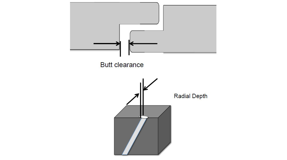
The radial clearance is the difference between the groove depth and ring width, which can be measured by a vernier caliper
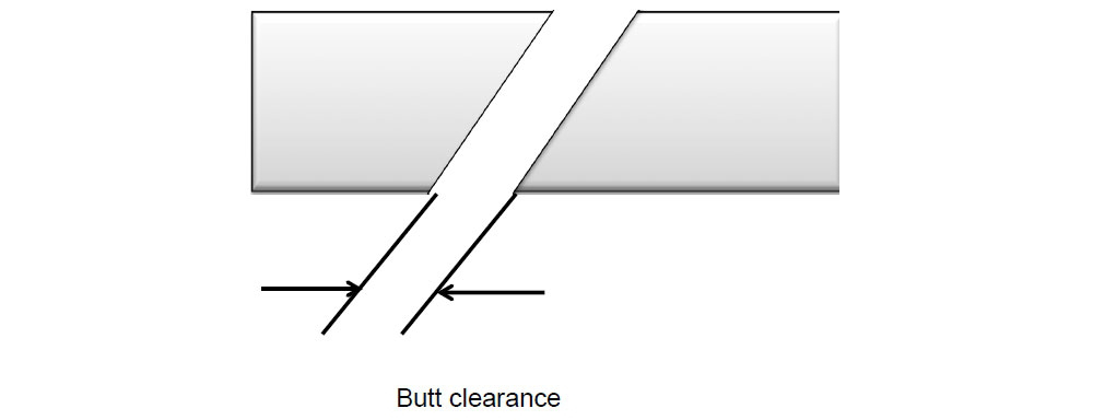
Butt clearance:

 It is the clearance between the end butt of the ring inside the liner.
The ring is placed inside the liner and the impression can be taken on a paper by applying Prussian blue paste at the butt ends. The gap between the impressions can then be measured.

CPR ring: 

The controlled pressure relief ring is fitted in the MAN piston as a top ring. The CPR ring has “S” shaped butt joint with six controlled pressure relief grooves milled across the face. Measure the radial depth of the grooves butt clearance at the S joint.

Comments


  1. Hey what a brilliant post I have come across and believe me I have been searching out for this similar kind of post for past a week and hardly came across this. Thank you very much and will look for more postings from you Best diamond huggie hoops Services Provider

    ReplyDelete
  2. Thanks for sharing the best information and suggestions, it is very nice and very useful to us. I appreciate the work that you have shared in this post. Keep sharing these types of articles here.Celeste Satin Suit Blazer Online

    ReplyDelete
  3. This post is really awesome. Genuinely i like this blog. It gives me more useful information. I hope you share lots of things with us .taparia tools distributors in bangalore

    ReplyDelete

Post a Comment

If you have any doubts.Please let me know

Popular posts from this blog

Differences between MC/MC-C and ME/ME-C engines

The electrohydraulic control mechanisms of the ME engine replace the following components of the conventional MC engine: Chain drive for camshaft Camshaft with fuel cams, exhaust cams and indicator cams Fuel pump actuating gear, including roller guides and reversing mechanism Conventional fuel pressure booster and VIT system Exhaust valve actuating gear and roller guides Engine driven starting air distributor Electronic governor with actuator Regulating shaft Engine side control console Mechanical cylinder lubricators. The Engine Control System of the ME engine comprises: Control units Hydraulic power supply unit Hydraulic cylinder units, including: Electronically controlled fuel injection, and Electronically controlled exhaust valve activation Electronically controlled starting air valves Electronically controlled auxiliary blowers Integrated electronic governor functions Tacho system Electronically controlled Alpha lubricators

Why is a man hole door elliptical in shape?

Any opening in a pressure vessel is kept to a minimum and for a man entry an elliptical hole  is lesser in size than the corresponding circular hole. More over it is prime concern to have a  smoothed generous radius at the corners to eliminate stress concentration. Hence other  geometrical shapes like rectangle and square are ruled out.  To compensate for the loss of material in the shell due to opening, a doubler ring has to be  provided around the opening. The thickness of the ring depends on the axis length along the  dirrection in which the stresses are maximum and the thickness of the shell. It is important to  align the minor axis along the length of the vessel, as the stress in this direction is  maximum. Longitudinal stress: Pd/2t where P= pressure inside the vessel, d= diameter of the arc, t=  thickness of the shell plating  Circumferential stress: Pd/4t  More over a considerable material and weight saving is achieved as minor is along the  direction of maximum stress.

Shell Expansion Plan

It is a two dimensional drawing of a three dimensional surface of the ship’s hull form. This plan is very useful for the following information:It is used for marking the location of a hull Damage on this plan by identifying the strake number , letter and frame number so that the exact location of the damage and also suggested repairs are marked in a localised copy. The shell expansion can be used for finding areas of painting surfaces such as topside, boot topping and bottom areas by applying Simpsons rules directly.  In the shell expansion the vertical scale used is different from the horizontal scale and a suitable adjustment has to be made when calculating areas. This becomes useful in solving disputes concerning areas of preparation and painting. It gives information on the thickness of the original strake which is indicated by the number in the circle shown in the strake.  The quality of steel used is also shown by letters A,B,D E and AH, BH,DH, EH.