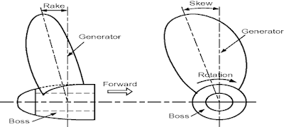
RAKE and SKEW of propeller


RAKE:

  • When the propeller is viewed from sideways, we see that the blades of the propeller are not perpendicular to the surface of the hub. It is ‘tilted’ at an angle either towards the fore-end or the aft end of the ship. This is termed as Rake. 
  • One of the biggest reasons for the rake is allowing higher clearance between the blades and the vicinal hull surface. If the blade tip happens to be very close to the hull plating (which is very prone in case of no or little raked ones), there is a chance of induced vibration due to ship propeller action. 
  • When the blade is raked forward, that is in the direction of the shaft axis towards fore-end, it is called Negative Rake. Conversely, when it is raked aft, it is called Positive Rake 

SKEW: 

  • When we look at the ship propeller surface from behind). The blade appears to be ‘Skewed’, that is, bent or twisted sideways. 
  • After years of experimentation, analysis and sea trials, it was observed that aptly skewing a ship propeller nullifies or considerably minimises the extent of unsteady hydrodynamic loading in this flow field. This indirectly has positive effects in reducing resistance due to viscous ‘drag’ effects. It also reduces propeller-induced vibrations. 
  • Reduction in unsteady bearing forces and moments. 
  • Reduction in unsteady pressure forces.

Comments

Popular posts from this blog

Differences between MC/MC-C and ME/ME-C engines

The electrohydraulic control mechanisms of the ME engine replace the following components of the conventional MC engine: Chain drive for camshaft Camshaft with fuel cams, exhaust cams and indicator cams Fuel pump actuating gear, including roller guides and reversing mechanism Conventional fuel pressure booster and VIT system Exhaust valve actuating gear and roller guides Engine driven starting air distributor Electronic governor with actuator Regulating shaft Engine side control console Mechanical cylinder lubricators. The Engine Control System of the ME engine comprises: Control units Hydraulic power supply unit Hydraulic cylinder units, including: Electronically controlled fuel injection, and Electronically controlled exhaust valve activation Electronically controlled starting air valves Electronically controlled auxiliary blowers Integrated electronic governor functions Tacho system Electronically controlled Alpha lubricators

Why is a man hole door elliptical in shape?

Any opening in a pressure vessel is kept to a minimum and for a man entry an elliptical hole  is lesser in size than the corresponding circular hole. More over it is prime concern to have a  smoothed generous radius at the corners to eliminate stress concentration. Hence other  geometrical shapes like rectangle and square are ruled out.  To compensate for the loss of material in the shell due to opening, a doubler ring has to be  provided around the opening. The thickness of the ring depends on the axis length along the  dirrection in which the stresses are maximum and the thickness of the shell. It is important to  align the minor axis along the length of the vessel, as the stress in this direction is  maximum. Longitudinal stress: Pd/2t where P= pressure inside the vessel, d= diameter of the arc, t=  thickness of the shell plating  Circumferential stress: Pd/4t  More over a considerable material and weight saving is achieved as minor is along the  direction of maximum stress.

Shell Expansion Plan

It is a two dimensional drawing of a three dimensional surface of the ship’s hull form. This plan is very useful for the following information:It is used for marking the location of a hull Damage on this plan by identifying the strake number , letter and frame number so that the exact location of the damage and also suggested repairs are marked in a localised copy. The shell expansion can be used for finding areas of painting surfaces such as topside, boot topping and bottom areas by applying Simpsons rules directly.  In the shell expansion the vertical scale used is different from the horizontal scale and a suitable adjustment has to be made when calculating areas. This becomes useful in solving disputes concerning areas of preparation and painting. It gives information on the thickness of the original strake which is indicated by the number in the circle shown in the strake.  The quality of steel used is also shown by letters A,B,D E and AH, BH,DH, EH.